Find

Main | Find

Find

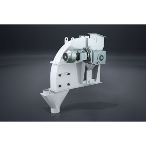
It is designed to convey all powdered and granulated raw material and finished products of less adhesive at horizontal/limited angular position to meet all industrial sectors need. It is generally used underneath of the product silos for conveying product and makes dosing. The dosing process speed is adjusted by using inverter.

Working Principle

Due to its cylindrical form, it provides possibility of conveying of product at higher speed and at severe (perpendicular) angles.

0.00 KZT

It is used to discharge or interrupt the flow of free flowing raw material or products to any desired terminal.

Working Principle

The product flow is allowed or stopped by opening and closing the sliding gate, which has a leakage-proof feature. The pneumatic and manual types can be manufactured. The pneumatic type gate can be automatically operated and connected to the automation system. The flow rate of a manual type-sliding gate is adjusted by means of an adjusting screw.

0.00 KZT

It is used to convey the granular and grinded products horizontally for collecting, distributing, mixing and tempering processes.

Structure

  • Mechanical
  • Semi-cylindrical troughs and out-wall installed ball bearings
  • Plastic bushing installed intermediate bearings allows free maintenance
  • Spiral
  • The screws or spirals are welded on a pivot in a regular pitch
  • Types of drive
  • Motor with coupling
  • Flanged motor with coupling
  • Chain driven type motor
  • Special designs (at request)
  • Stainless steel construction
  • Variable screw pitches
  • Special painting applications
  • With feeding box
  • The modular system allows it to be used for many and variable applications.
0.00 KZT

It is used to divert the product both for pressurized conveying and for aspirated pneumatic conveying systems.

Working Principle

The product, which enters the gate from its inlet, is diverted to any desired direction according to the process by using a piston driven gate.

0.00 KZT

A low pressure and high flow rate radial type fan is used in different industrial sector where the ventilation systems need.

Working Principle

The low pressure fans provides low pressure in conveying systems and cereal cleaning machines in the cereal processing plants to prevent dust leaking.

0.00 KZT

It is used to convey granular or ground products in the system where at high pressure and low or medium flow rates are required.

Structure

The fan body and the impeller are precisely manufactured and fitted on a steel foundation. The unit is designed and outfitted with special blades and can be easily dismantled and reinstalled, if high rpm is required In case of requirement, it can be supplied by installing soundproof isolation.

0.00 KZT

It is used to feed the product regularly and without leaking out into pneumatic conveying pipes at the pneumatic conveying systems. Easy assembling including drive unit and chain coupling in installation group

Working Principle

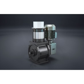
The product, which enters on the airlock, flows into chambers, than will be discharged into conveying channels. The chambers are made by fixing wings on rotor shaft. Because of the precise and standard tolerances between the body housing and the rotor wings the pressurized air is prevented from leaking into the product inlet so that high efficiency and proper operation is provided. The system can be used up to 1 - 1.5 bar air pressure. By using special seals, the product is prevented from entering the shaft housing and bearings.

0.00 KZT

It is used to centrifugally separate dust-air mixture.

Working Principle

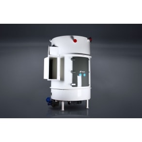
The dust-mixed conveying gas is started turning by transferring it into a separator by means of a spiral construction. Gas is forced in to rotate in the cyclone. Due to the centrifugal forces, dust parcisles are carried to the surroundings. Pushing the gas to inward from the backward crastes a vortex. The air is separated from the dust particle, which are forced downwards along a spiral way because of friction of the air against the wall.

0.00 KZT

It is used mainly to convey all types of bulk material in the food industry.Adjustable by using ZT series of chain installation

Structure

An enclosed, rectangular cross - section, made of steel casing is furnished with an endless chain equipped with flights.

Working Principle

The lower chain section moves along the bottom of the steel casing and conveys the materials. The return part of the chain is guided along the central rail. The chain runs around a sprocket at the outlet end and around and idler at the inlet end. The material and chain travel along at a uniform speed. The product is dropped through the chain at the outlet and flows out of the conveyor. The design of the chain lets several inlets, which can be arranged along the entire length of the conveyor. It is also possible to install outlet gates, which can be manually and remotely controlled.

The chain

The most important and working part of a chain conveying system is “chain”. In order to obtain the necessary high tensile strength and wear resistance of the chain, it is manufactured in a special forging and hardening process.
For special application at food processing and handling, the stainless steel chain can be supplied.

0.00 KZT

Belted bucket elevator is very ideal for vertical conveying of bulk materials or products, which have particle size up to 50 mm.

Structure

  • The whole body is fabricated from steel sheet. Because of international safety regulations, inspection and installation covers should only be opened by suitable tools.
  • The driven system is designed to move only in one direction.
  • Reverse movement isn’t permitted.
  • For special applications, mostly worn surfaces are supported (covered) with replaceable plates.

Drive selection;

  • With direct-coupled reducer motor
  • With chain or belt-pulley driven reducer system
0.00 KZT

It is used to separate air from the product, which is discharged from a cyclone separator into pneumatic systems. It is installed underneath the cyclone separators and air filters. It works with the negative pressure as well as an air seal against leakage.

Working Principle

From the air lock inlet the air-product mixture enters the chambers, which are created by fixing blades (wings) on the rotor shaft. Due to the precise and standard tolerance between the body housing and the rotor, the product is separated from air and discharged regularly without any leakage. Due to the air leakage-proof feature of the air lock, the escape of product is prevented together with air, which is sucked by an existing collector.

Features & Advantages

Provides perfect separation of air and dust particles in the cyclone due to its very precise fabrication
Provides various drive possibilities, such as:
- By geared motor, direct flanged
- By geared motor, with coupling
Several air locks can be coupled together.

0.00 KZT

Suitable to separate dust and other particles suspended in air of cleaning department aspirator system before being discharged to the outside with a bottom scraper.

Effective Factors

  • The size of particles, paint pigments, pneumatic system of the mill, cleaning, aspiration
  • Physical composition of dust
  • Dust concentration in the untreated air (aspiration)
  • Electrostatic charge:
  • The given filter dimensions are taken into consideration in accordance with a 2.4 meter long bag.
  • The rate of flow changes depending on the rate of filtration area for other length of filter bags.
  • The air needed for cleaning and pneumatic control purposes of the Jet Plus Filter is supplied by a blower, which produces dry air
  • The air needed for cleaning and pneumatic control is obtained directly through a connection between the filter and the blower without using an air tank
  • The Jet Plus Filter is combined with a pneumatic control unit, which is actuated by an electronic control unit, quick ventilation valves (nozzles) and venture pipes

Working Principle

N1 Filtration phases in the N1 bag: The dusty air is purified (filtrated) in the outer surface of the hose type filter bag. N2 Final cleaning phase in the N2 bag: Dust loaded outer surface of the filter bags is cleaned respectively by blowing air from inside of bags. The accumulated dust is discharged out of the air lock due a scraper.

Features & Advantages

  • The filter can be used in the pressurized and vacuum systems. The cleaning of hose type filter bags is carried out by air at 0.5 bars, which is free of oil and water
  • The consumption of the cleaning air is found by this formula: 30 - 40 NLt (Newton liter) x bag x blow
  • The optimal flow geometry of the cleaning air route shows as mentioned below:
  • The loading capacity of filter for each product
  • The max cleaning capacity for each filter bag
  • The highest cleaning ratio of cleaned air
  • The filter body is combined with cleaning air tank
  • Therefore, there is no need for an additional air tank
  • The important criterions of filter loads
  • In addition to the given effective values at right, the loading of filter depends on some other factors such as, chemical reactions, drying, filtration process, etc. As an example, at wheat cleaning process, in a filter with a 2.4-meter long bag, maximum loading for aspirator would be 9 cubic meters per minute per square meter.
0.00 KZT

The weighing unit is designed and manufactured to weigh granule and powdered product during the continuous flow by batch at high capacity. It is used in flour milling sector, cereal processing and storage plants, cereal trading and cleaning complexes, raw material storage silos, in harbour cereal storage facilities.

Working Principle

  • Pans and covers have a perfect hygienic and hermetic feature and both hold Alapala’s patent.
  • For higher capacities a two pan model scale is available.
  • The weighing process is made by two Load Cells “OFF CENTER” type.
  • All operations and controls are carried on by appropriate PLC programme.
  • Each scale can be connected to the Communication Centre and Extraction Control System both one by one and as a group of scale.
  • Data interchange possibility between Scale, System and Operator.
  • Measuring possibility of flow rate at continuous flow.
0.00 KZT

It is used to measure preciously the weight of cereals during flow.

Working Principle

  • The measuring process is carried out by a PLC programme.
  • The programme provides data for product flow, communication between pneumatic controlled caplet and load cell, special inlet spout which can give quick adjusting possibility of very high and very low flow rate.
  • If the automatic dosing machine will run individually, each machine should have its own PLC, in case, they will work as a group, for each group one PLC unit shall be installed.
  • All data are registered in central control room system.
0.00 KZT

It is designed to measure continuously material throughput rate and weight for monitoring of granular materials.

The accurate information is obtained regarding mill yield by installing a group of scales on different product lines.

Working Principle

The existing product in the upper bin is conveyed into a weighing chamber through the pneumatically operated gate in the inlet box. Meanwhile, the weighing chamber gate is kept at the closed position. The required weight is measured by means of load cells and this information is fed into PLC system. By means of PLC system, the weighing chamber gate is opened and the product is dumped into the lower bin. When the batch of product is finished in the lower bin, the capacitive level control switch feeds back information to the PLC system and filling process is repeated.

0.00 KZT